
Radiometric Calibration
Remote sensing sensors, depending on their type, might produce a single value per measurement, such as a point distance, a 2D data matrix, such as a single band image, or a 3D data cube, such as a multiple-band image. The FOV of the sensor determines the spatial extent that is going to be mapped on a two-dimensional array. Each element on the data arrays contains a DN value proportionate to the electric charge received at capture time. However, the values do not necessarily express the objects' actual radiation or reflectance due to several error interferences either by sensor operation or environmental factors referred to as noise. In satellite-based sensors, especially state-sponsored satellites, all calibrations and corrections are usually scrutinized prior to launch and are available as metadata to the users. However, private platforms tend to be more vulnerable to miscalibration effects.
Sensor noises emerge from the electrical, mechanical, and physical arrangement of the sensors that alter the DN values one way or another. For example, some sensors have a gradual increase in DN values horizontally or vertically regardless of the input radiance due to electrical arrangements of photoreceptors. Besides the electronic noise, the lens and other structures within the sensor might affect the DNs. Vignetting is one of the well-known and prominent effects that is defined as a radial reduction in brightness from the center towards the image edges[1]. For high-quality fixed focal length lenses, vignetting can account for 30–40% of the intensity difference, and for zoom and wide-angle lenses, it might be even higher[2].
Dark current is another sensor error source. In theory, for example, if we take an RGB picture in an absolutely dark place, all pixels must be zero. However, in practice, this is not the case due to the noise in circuits, the Charged Couple Device (CCD) noise, working temperature, and other uncertainties. This noise, which can happen in any sensor type, is called dark current or black level noise[3]. However, the amount of this noise is usually negligible compared to other error sources, if the working temperature and the circuits are almost constant.
Understanding the error source and compensating for their effect helps produce more repeatable and accurate results. Most manufacturers provide adjustment matrixes that correct the vignetting and noise effects per band per pixel. Micasense company, for instance, provides a formula for compensating the sensor’s black-level, the sensitivity of the sensor, sensor gain and exposure settings, and lens vignette effects in their RedEdge multispectral camera [4].
Removing the environmental-dependent errors is the next step. The environmental effects can cause two or three times more errors than the sensor effects[5]. Environmental calibrations are adjustments needed for producing repeatable data in different environmental conditions. Most of the corrections that are required for satellites are negligible for low altitude flying remote sensing platforms[5]. For example, scattered or absorbed radiation from/by the particles in the atmosphere is usually ignored in lower altitudes. However, other corrections might become necessary when flying with UASs. The solar position with respect to the flight heading and the camera-object angle is an influential factor on the energy received by the sensor[6]. Hot spot in antisolar point (a point on the ground that falls on the camera-sun line) is another issue that is not a very severe problem in satellite imaging [7] but might become a critical problem in UAS imagery. This problem causes an overexposed area in the antisolar point of the image that gradually decreases by distance [8] and it can happen even in line-scanner sensors. . Although none of the papers in this review have considered the effects of the sun angle and bidirectional reflectance distribution function (BRDF) on the images, the literature suggest the effect is not negligible[9] [10].
Besides the calibrations discussed, the weather condition plays a critical role in the accuracy and the quality of the data gathered. For example, on partly cloudy days, radiance values might change drastically in a glimpse reducing data reliability. A study showed that poor weather conditions (cloudy, precipitation) deteriorate the final quality and accuracy of the photogrammetric product by an average of 25% [11]. Even in clear sky condition, changing irradiance from the sun might affect the results. The two most common used methods for dealing with this situation are 1) using reference reflectance panels, and 2) using ambient radiance sensors. The reflectance of reference panels is measured twice, once before and once after each flight, to compensate for the overall irradiance change. However, any solar irradiance changes during the flight will remain uncaught. Using ambient radiance sensors might alleviate this problem. However, if used in constant radiance conditions, sunny sky for example, it can adversely affect the image calibration process[12]. Figure 6 summarizes the noise discussed above.
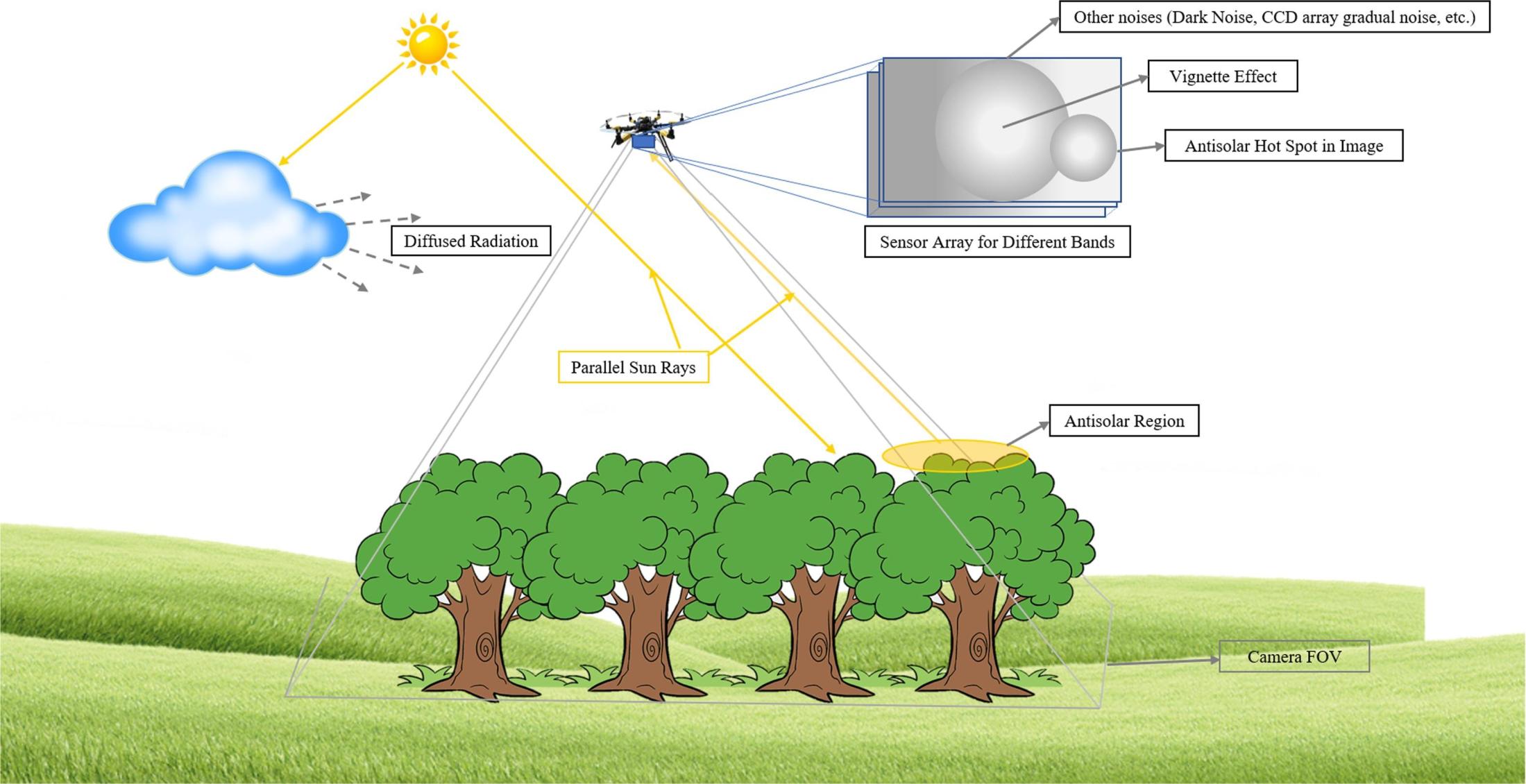
Figure 6- Types of noises affecting a remote sensing sensor; environmental Noises and Sensor based noises.
Converting the adjusted digital numbers to a meaningful physical unit is the next step. The SI unit of radiance is watt per steradian per square meter (W·sr−1·m−2), while a DN has no unit. When DNs are converted to radiance, they can be used in every condition, and long-term comparisons will be possible. Usually, the sensor companies provide metadata that contains the parameters and information required for converting the DN to radiance. However, some studies have shown that the factory-provided adjustment parameters of a sensor may change as it is utilized in real-world conditions, so a recalibration process is recommended[13]. A lamp generating homogeneous known wavelengths[3] or Lambertian panels [2] can be used for recalibrating a sensor. The sensor's response linearity and range are two essential factors that should be considered during recalibration[3].
Calibration of thermal cameras is slightly different from optic cameras, and usually, ground-based calibration targets (with known temperature) [45] measured by handheld infrared thermometers [79] are reported to be used for temperature adjustment. An accurate calibration guarantees the reliability of data and reduce the impact of errors on the modeling and interpretation. So, it is important to perform an accurate calibration before data extraction and interpretation.
References
[1] J. Kelcey and A. Lucieer, “Sensor correction of a 6-band multispectral imaging sensor for UAV remote sensing,” Remote Sensing, vol. 4, no. 5, pp. 1462–1493, 2012.
[2] D. B. Goldman, “Vignette and exposure calibration and compensation,” IEEE transactions on pattern analysis and machine intelligence, vol. 32, no. 12, pp. 2276–2288, 2010.
[3] H. Aasen, A. Burkart, A. Bolten, and G. Bareth, “Generating 3D hyperspectral information with lightweight UAV snapshot cameras for vegetation monitoring: From camera calibration to quality assurance,” ISPRS Journal of Photogrammetry and Remote Sensing, vol. 108, pp. 245–259, 2015.
[4] MicaSense, “RedEdge Camera Radiometric Calibration Model,” MicaSense Knowledge Base, 2020. https://support.micasense.com/hc/en-us/articles/115000351194-RedEdge-Camera-Radiometric-Calibration-Model (accessed Dec. 01, 2020).
[5] Y. Guo, J. Senthilnath, W. Wu, X. Zhang, Z. Zeng, and H. Huang, “Radiometric calibration for multispectral camera of different imaging conditions mounted on a UAV platform,” Sustainability, vol. 11, no. 4, p. 978, 2019.
[6] A. Sekrecka, D. Wierzbicki, and M. Kedzierski, “Influence of the Sun Position and Platform Orientation on the Quality of Imagery Obtained from Unmanned Aerial Vehicles,” Remote Sensing, vol. 12, no. 6, p. 1040, 2020.
[7] J. M. Chen and J. Cihlar, “A hotspot function in a simple bidirectional reflectance model for satellite applications,” Journal of Geophysical Research: Atmospheres, vol. 102, no. D22, pp. 25907–25913, 1997.
[8] M. Pepe, L. Fregonese, and M. Scaioni, “Planning airborne photogrammetry and remote-sensing missions with modern platforms and sensors,” European Journal of Remote Sensing, vol. 51, no. 1, pp. 412–436, 2018.
[9] W. H. Maes and K. Steppe, “Perspectives for remote sensing with unmanned aerial vehicles in precision agriculture,” Trends in plant science, vol. 24, no. 2, pp. 152–164, 2019.
[10] B. Stark, T. Zhao, and Y. Chen, “An analysis of the effect of the bidirectional reflectance distribution function on remote sensing imagery accuracy from small unmanned aircraft systems,” in 2016 International Conference on Unmanned Aircraft Systems (ICUAS), 2016, pp. 1342–1350.
[11] D. Wierzbicki, M. Kedzierski, and A. Fryskowska, “Assesment of the influence of uav image quality on the orthophoto production,” The International Archives of Photogrammetry, Remote Sensing and Spatial Information Sciences, vol. 40, no. 1, p. 1, 2015.
[12] MicaSense, “Capturing Multispectral Data in Ideal and Adverse Lighting Conditions,” MicaSense, 2020. https://micasense.com/capturing-multispectral-data-in-ideal-and-adverse-lighting-conditions/ (accessed Dec. 07, 2020).
[13] B. Mamaghani and C. Salvaggio, “Multispectral sensor calibration and characterization for sUAS remote sensing,” Sensors, vol. 19, no. 20, p. 4453, 2019.